| | 
This is my version of the carbon canister removal and bypass for a 1992 Nissan 300ZX twin turbo. I can not comment on this job for the non-turbos (NA’s) other than to say that I think the job should be easier without the intercoolers in the way. I make no claims that this is the only way to do the job, other than I practiced due diligence in my research and pass on the info in good faith. You can skip directly to the “How To” section if you just want the nuts and bolts part of the explanation.
What is the carbon canister?
Cars have three main sources of air pollution, along with the federally mandated systems installed to reduce these emissions. First, the crankcase emissions are returned to the engine by the positive crankcase ventilation (PCV) system. Second, the tailpipe exhaust emissions are controlled mainly by the exhaust gas return (EGR) system, the catalytic converters, and by electronic control unit adjustments (ECU) to the engine.
Finally, fumes from the gas tank are sealed from the atmosphere by a gas cap, and stored in a carbon canister (CC) for reburning when the engine is running. The CC, gas cap, lines and controls are sometimes collectively referred to as the EVAP (evaporative) system. A car’s EVAP system is passive. The gas fumes are trapped in the carbon canister while the car is at rest, then purged back into the intake system using vacuum pressure when the car is running.
In the z32, the carbon canister (CC) is located in the driver’s side (DS) fender well, behind the stock intercooler (IC). The CC does not effect performance or exhaust emissions in any way.
If you have a 1996 Z, read the tech section at the end.
Why remove the carbon canister?
Weight reduction is minimal, the canister only weighs a couple of pounds, but every little bit helps. As a potential source of vacuum leaks, there are several separate lines and even the canister itself can crack with age. A failed, damaged or clogged canister is a known cause for the engine to run poorly. Eliminating unnecessary vacuum lines also simplifies future trouble shooting and maintenance.
The canister sits right behind the DS IC. Removing the CC improves airflow around and through the IC, although I’m not sure if this has ever been shown to have a measurable effect.
Eliminating the CC does mean you will be venting some gas tank fumes to the atmosphere. Since this is illegal the instructions here are for discussion purposes only, and not intended as a recommendation or endorsement to doing anything to your car that will increase air pollution. A malfunctioning gas cap will release much more hydrocarbons into the atmosphere than the CC bypass as described here.
When to do it?
Whenever the front fascia (FF) is off, or whenever a problem is suspected with the system (read about the temporary diagnostic bypass in the tech section at the end to test if your system is working). I removed my CC while YugoBernie installed my new Greddy side mounted IC’s.
Tool needed
Simple hand tools, 10mm socket, curved long needle nose pliers, sharp knife, a one foot section of 6mm vacuum line (I prefer silicone), one vacuum plug or make your own.
Difficulty
If the front fascia is already off, then a 2 out of 5. Time is about an hour, again, not counting the labor to remove the FF.
How to do it
Removing the front fascia is the hardest part, and it is not that hard although it helps to have two sets of hands.
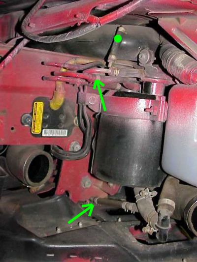
After the FF and DS intercooler are removed, you will see the black, cylindrical CC in the wheel well looking like the photo below. My IC’s were being swapped, so I do not know if the job is possible while leaving the IC in. Bernie's opinion and mine is that pulling the IC is not hard, and doing so yields a lot of room to work, so we recommend it.
Ignore the red overspray paint :c) That’s what happened with a sorry-ass FF paint job. The large black open hose to the left is the IC inlet hose. The white plastic tank on the right edge is the radiator overflow tank. There is a slice of the IC outlet hose in seen in the bottom, right corner. So if the IC were in place, the airflow would flow from left to right in this picture.
There are four lines connected to the top of the tank, and one large hose that splits into two coming out of the bottom. Once the canister and all the hoses are removed, the green arrows show the new connection you will make with about a one-foot section of six-millimeter vacuum hose. The green dot shows a vacuum nipple that must be capped. Everything else can be left open.
Remove the single bracket bolt holding the circular, metal retaining strap around the CC. The bolt is a tight fit because of the overflow tank, so I loosened the nearest mounting bolt on the radiator overflow tank, too.
Slide the clamps off that are holding the hoses onto the CC, with the curved needle nose pliers. There is only one hard line you have to identify, and that is the fuel tank line on top. Mark or tag it somehow, or later you can blow in it with your gas cap off and confirm there are bubbling sounds or fumes coming out of the gas tank inlet. Do not top off your gas tank before doing this, or blowing in the line even a little bit will overflow quite a bit of gas onto your garage floor (sorry about that Bernie).
The four connections to the top of the CC are labeled TWICE on the canister. First, as a decal on the top surface as shown, “signal VC, purge, fuel tank, and purge (again),”
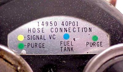
and again on the side of the CC where the writing is part of the tank.
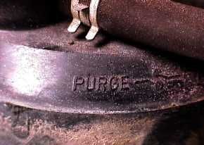
You only have to identify the fuel tank line. On my car, a ’92 TT, the fuel tank vent line was the most outboard line coming off the three hard lines of the metal galley.
Remove or cut all the hoses off, bend the bracket open and pry out the CC. Finish removing the CC mounting bracket by removing the three,10mm bolts that hold it onto the frame rail. Remove all the remaining hoses that were connected to the CC. The large bottom hose from the canister splits into two. Note where the bottom small hose disappears into the frame rail. This will be the connection for the fuel tank vent line from above.
Contrary to popular belief, the large bottom tube connected to the CC is not a vent tube for outward gasses, but an air INTAKE tube. I believe the small tube that branches off was a drain tube for water condensation. The large, bottom tube continues up high and connects behind the CC into the frame rail. Some folks advocate connecting the fuel tank vent line to this tube, instead of the small, bottom tube as I suggest.
I chose a to vent the fuel line through the small bottom metal line for these reasons: I believe the larger tube up high was originally an intake to the canister, not a vent tube carrying gasses away. Even though folks have viewed venting the gas fumes into the frame rail as “safe,” I believe it is much safer to disperse the fumes to a part of the car with more ventilation. Second, there are cars that have had their CC clogged by spiders or mice building their homes around the larger pipe, so that means the fuel vent line could get clogged if this route was chosen. Finally, my connection maintains a sealed system unless enough positive pressure occurs to overcome a small bleeder valve used at the end of the fuel tank line’s new connection .
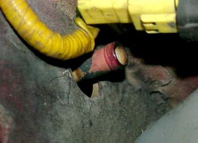
 The nice part about using the smaller nipple at the bottom for the fuel tank connection is that it ends in a simple, one-way rubber bleeder, flap valve that is closed. Blowing on this line shows the valve to have little or no back pressure. The nice part about using the smaller nipple at the bottom for the fuel tank connection is that it ends in a simple, one-way rubber bleeder, flap valve that is closed. Blowing on this line shows the valve to have little or no back pressure.
This flap valve empties well out of the way under the car and I have not noticed even the slightest whiff of gas with the fuel vent line connected this way. However, this is winter, so summer may make a difference with higher temperatures producing more fuel evaporation, I dunno.
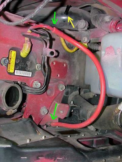 Here is the overall view with the CC removed and the fuel vent line rerouted with a red vacuum hose. The new connections are shown by the green arrows. Leave some slack for the IC that installs in front of the red hose. The yellow arrow shows an open nipple on the air intake tube that that must be sealed. Here is the overall view with the CC removed and the fuel vent line rerouted with a red vacuum hose. The new connections are shown by the green arrows. Leave some slack for the IC that installs in front of the red hose. The yellow arrow shows an open nipple on the air intake tube that that must be sealed.
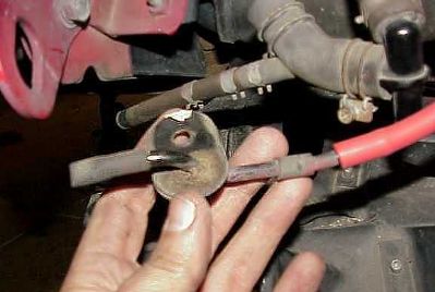
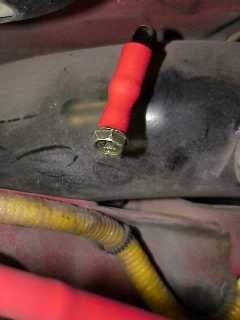 I didn’t feel like making a run to the auto parts store just for one vacuum cap, so I made my own by simply putting a screw in short piece of vacuum hose, as shown. I used sealant around the screw threads and put a twisty tie on it after the pic was taken, since the cap should be made as permanent as possible. I didn’t feel like making a run to the auto parts store just for one vacuum cap, so I made my own by simply putting a screw in short piece of vacuum hose, as shown. I used sealant around the screw threads and put a twisty tie on it after the pic was taken, since the cap should be made as permanent as possible.
You can get to this cap in the future if necessary by removing the two screws that attach the turn signal light, so no big deal. Otherwise it is hidden and will not show, in case you have a show car or are worried about appearance. The work is now done in the fender well.
Time to move under the hood.
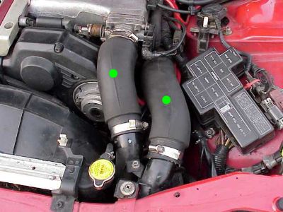
Remove the two, large intercooler hoses on the DS, shown by the green dots in the photo. These hoses are lot easier to remove when warm. You can either run the engine or warm the hoses with a hairdryer, if necessary.
Now look down toward the front of the car, just outside of where the large IC hose ran from the turbo down to the IC. Find the metal vacuum galley as shown.
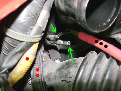
Pull the two vacuum lines that were connected to the nipples shown by the green arrows. You can leave these nipples open because they aren’t connected to anything in the DS fender well any more. The top, open nipple was connected to the throttle body, the bottom nipple to the balance tube. The vacuum marked with the three black dots goes to the recirculation valve on the DS, so leave that untouched.
The line with the corrugated padding marked with the two red dots is the fuel vent line. That is the line that was left hooked up in the DS fender well, so leave that one alone, too. The yellow line with the single red dot is part of the electronics to the supplemental restraint system (SRS) otherwise known as the air bag system. Definitely don’t touch that.
Next trace back to where the vacuum lines are connected under the hood. The top line went underneath the throttle body (TB), which is very easy to see because you already have the IC hoses removed,and is shown two photos below. The bottom vacuum line went to the back of the engine and connected to this nipple on the balance tube.

Basically, you can either cap or connect the TB and balance tube vacuum nipples. I prefer to connect them with a vacuum line and here is why – the line “marks” your vacuum sources better for future reference. A cap is more “out of sight, out of mind” and may come back to haunt you. A vacuum line is easier to pull than a cap, which is relevant to me since I use the TB connection for “water cleaning” my intake.
Some folks believe caps are more prone to failure. Another reason is convenience, the vacuum line that is already connected to the balance tube in the back is long enough to do the job. Just curve it around and connect it to the TB at the other end. I trimmed a few inches off the line for a nice fit. Here is a photo of the vacuum line sweeping around from the balance tube in back. The arrow shows the connection to the TB. The green dots mark the other vacuum line that goes to the recirculation valves that was already mentioned above and is NOT involved in any part of this job.

If you prefer, you can buy vacuum caps at any auto parts store and cap the nipples instead. Read the "counterpoint" link at the end of this articles and form your own opinion.
Reinstall the large IC hoses and you’re done. Your car should run now. If you blew a lot of air into the vent line it might take a few tries to start your car. You should start your car before putting the FF back in place, in case you find any leaks that need immediate attention.
I did this job in January 2004 and so far have no problems or glitches to report. My only reservation is to see if summer weather makes any difference, but I doubt it will matter. I’m taking my Z down to Florida for the races at Sebring in March, so I can post a follow up then.
Bypasssing the CC without removing the FF and comments about the 1996 Z with On Board Diagnostics II (OBD II)
Note that the hose connection between the TB and the balance tube under the hood can be done in just a couple of minutes at ANY time without removing the front fascia. This temporarily BYPASSES the CC, which can be a very helpful, “quick and dirty” diagnostic tool for eliminating the CC and its connections as possible sources of leaks or trouble. The use of an inexpensive vacuum gauge could also be very helpful during this test, as you could compare vacuum readings before and after this temporary bypass of the CC. If you isolate the CC as a cause of a problem, then you know you have to fix it or eliminate it, before actually taking the FF off.
Why not just bypass the CC with the hose from the TB to the balance tube and leave the CC in place? I dunno, I suppose you could. You could cap the vacuum galley next to the IC hose where you pulled the lines to eliminate any chance of fume return. However, I would still be worried about the fuel vent line connected to the canister as a “dead end.” Without any vacuum source connected to it, the canister would eventually clog and then the fuel tank would be sealed and ventless, which doesn’t sound good. Perhaps that is not an issue but if you bypass the CC by only making new vacuum connections under the hood, then I recommend this only as a TEMPORARY diagnostic tool. If this shows your evaporative system to be faulty, then go to the trouble to do it right and completely pull the canister afterwards. Clear as mud?
If you own a 1996 Z then your emissions control systems were impacted by the On Board Diagnostics II (OBDII) system. OBDIl periodically checks many emissions control functions not monitored by earlier years OBD. This check includes evaporative canister purge system and a fuel tank leak check.
A 1996 Z undergoing an OBD II check will NOT pass emissions testing if the EVAP system throws any of the error codes listed below. This does NOT effect the emissions as measured at the exhaust, but is simply an error code that states the EVAP system is not functioning properly, and therefore your vehicle could be releasing unburned gas fumes into the atmosphere. I do not know exactly how removing the CC in a 1996 Z throws error codes at the ECU or OBD II level, but I think it is fairly safe to assume that it does, especially when you see the OBD II error code possibilities below:
P1440 EVAP Control System (Small Leak) (Positive Pressure)
P1444 Canister Purge Volume Control Solenoid Valve
P1446 EVAP Canister Vent Control Valve (Close)
P1447 EVAP Control System Purge Flow Monitoring
P1448 EVAP Canister Vent Control Valve (Open)
P1490 Vacuum Cut Valve Bypass Valve (Circuit)
P1491 Vacuum Cut Valve Bypass Valve
P1492 EVAP Canister Purge Control/Solenoid Valve (Circuit)
Although the EVAP codes don’t cause any performance issues, they will keep you from passing emissions testing. Emissions problems need to be fixed before the code can be erased.
Click here to read some good counterpoints on this article.
| |